Interfacing a 5 Volt Incremental Encoder to 12 Volts
June 4, 2014
.
Interfacing to an Incremental Encoder using an Optoisolator
When I chose the PLC that I wanted to build incremental encoder applications around, The DL06 seemed like a perfect low cost option, but what I failed to notice was that it had a minimum 12V input requirement to turn on the DC inputs. No problem, I thought, I’ll just get production to build me some of those 5-26V incremental encoders that are so popular with the kids now days. I realized that plan was flawed once I saw how busy the production schedule was. It appears that word has gotten out that the QDI series of encoders are a great positional feedback option.
So what could I do? I already had 5V incremental encoders mounted on the motors. This carried the added bonus of the commutation tracks already being phased, meaning I didn’t have to worry about timing the Com tracks of the incremental encoder to the BLDC motor.
If only there was some way to turn a 5V signal into a 12V signal…
Well there is. You can use a device called an optoisolator, sometimes called an optocoupler, or photocoupler, although there are technically differences among these devices.
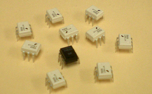
Here are some of them from my component stash. They seem to often come in white packaging.
My guess is that the white color is for better optical properties internal to the device, as white is much more reflective.
Looks like I only have one black sheep left in my flock.
An optoisolator consists of a light source on one side (usually an LED), and a phototransistor on the other. It should probably be mentioned that the “tail end” of an optoisolator can also contain other devices, like an SCR, Triac, or varistor. For what I needed, the transistor style output would work just fine.
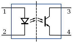
Each side of the device is electrically isolated from the other so there can be a 5 volt potential on one side and a 12 volt potential on the other, each having a separate a ground.
I also needed to use at least a 100 ohm resistor on the cathode side of the LED. This was done to limit the current though the optoisolator in order to keep from burning out the internal LED. The inputs on the PLC already have built in internal resistance, so no resistors were needed there. I just wired it in series between the +12V source and the input. The PLC’s common was wired to ground.
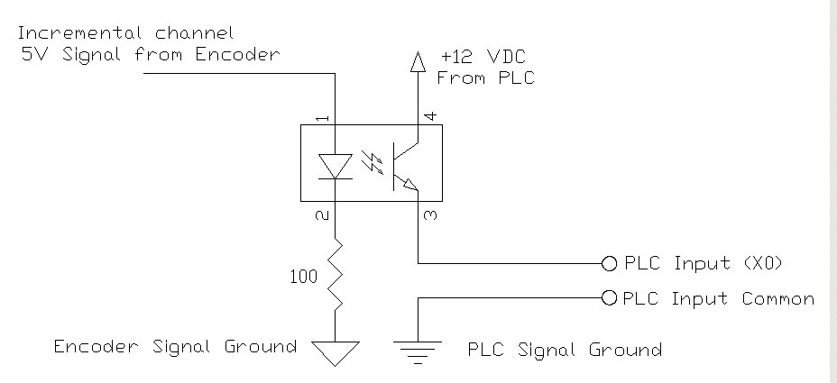
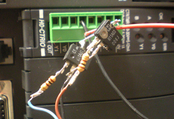
Below is a down and dirty”trial run” at interfacing to the PLC.
There is sometimes a need for a customer to separate out incremental and commutation signals with separate voltage supplies. Usually this is the case if the signals are running to two different devices, each with separate grounds. For example, having a drive and a controller that are separated by a great distance.
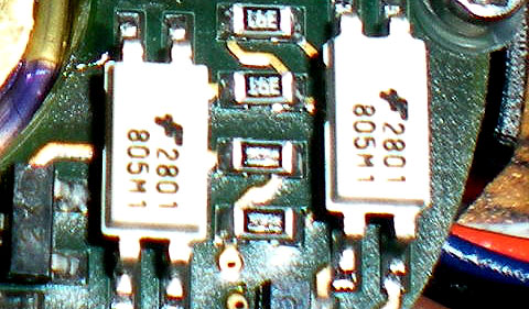
For these custom designs we have used the optoisolators internal to the encoder. Here they are in a smaller surface mount package.
While optoisolators can be a good solution to an incremental encoder voltage-interfacing problem, ordering an encoder like a 5-26 Volt QR145, or QR200 and NOT having to mess with interfacing makes a lot more sense.
You should also keep in mind that there is a real delay using devices like this that can result in positional error. For demonstration purposes, or slow movers, this may not matter, but if you are trying to keep a the reigns tight on a control loop, 20 uS or so of delay may be too much.
To find your multi-voltage encoder answers go to https://www.quantumdev.com

