Understanding Options on the QDH20 Industrial Rotary Encoder
November 20, 2013
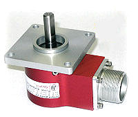
The QDH20 Industrial Rotary Encoder is an IP66 sealed encoder made for the rugged duty of an industrial application. Due to the huge array of configuration options, this optical encoder has over 200,000 possible ways that it can be configured.
While this is certainly an advantage to an end user that may be seeking just the right encoder, the sheer number of choices can make configuring a part number a confusing proposition. I am going to try to shed some light on the QDH20’s available choices in order to make things a bit more clear.
Mounting Options:
This refers to the style of the mounting “face” of the encoder. There are three basic types: Flange, Servo and Flex mount. These size of each of these types are referred to by motor sizing terminology. A “Size 20” mount is approximately two inches and a “Size 25” is about 2.5 inches.
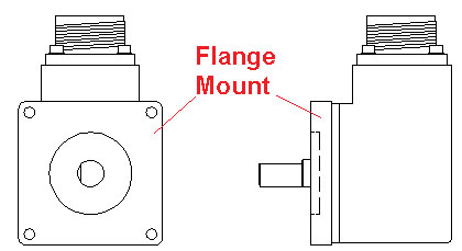
The flange mount is used when you are bolting directly to a surface. The flange surface is typically square with bolt holes in each of the four corners.
I am using CAD drawings for my examples as they are more readily available and easier for me to work with than photos.
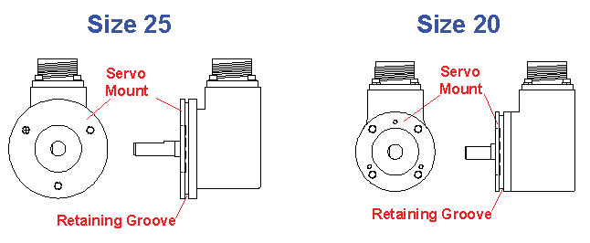
The servo mount is typically round and there is a built in retaining groove around the mounting edge. While it can be mounted using this edge, there are also three tapped mounting holes for the size 25 and a set of three and as set of four tapped mounting holes for the size 20, drilled into the face of the Servo mount.
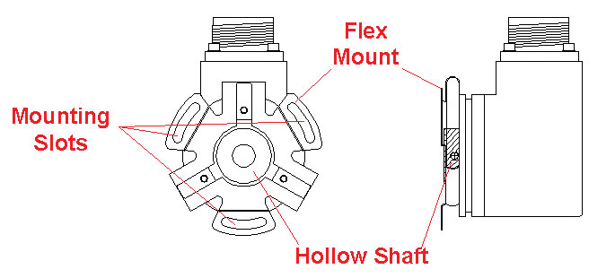
The flex mount has a spring steel mounting that allows for misalignment between the encoder and whatever it is mounted to. This is used with a “hollow shaft” option where the QDH20 encoder is receiving a shaft.
Mounting options may include a “pilot” or boss that is used to help align the encoder to a mounting surface. These are either female, which are recessed into the encoder housing, or male, which protrude out from the encoder housing.
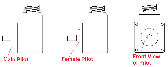
Quick Mounting Summary:
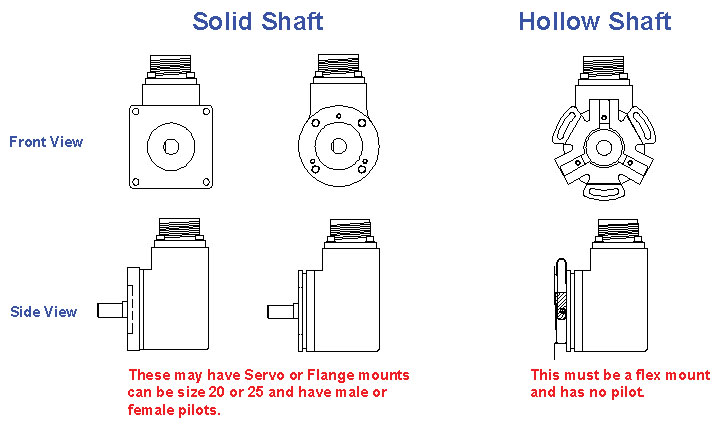
For QDH20 Mounting options, you can have a hollow shaft which can only be a flex mount, or a standard shafted encoder which can be either a flange mount (square) or a servo mount (round).
Both of these configurations may have either a male or female pilot.
Hollow shaft QDH20 encoders always have a flex mount and do not have a pilot.
Connector Housing Options:
The housing of a QDH20 encoder has two main considerations; the style of electrical connection to the encoder and the way these electrical connections exit the encoder.
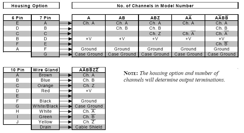
Electrical connections for the QDH20 encoder can be either a MS (Military Style) connector, or a flying leads type connection, referred to as a “wire gland”
The MS Connectors have three sizes 10 Pin, 7 Pin and 6 Pin. The number of output signals needed determines these connector sizes. For one channel single ended applications a six pin connector will work just fine, but for an application where all channels (AB &Z) and their complements are needed a ten pin MS Connector is a must.
Note that while it is possible to make an encoder that has a single output with a ten-pin connector, items like these are not part of the QDH20 standard offering. If a special QDH20 configuration is needed, Quantum Devices’ crack engineering team will typically be able to make it happen.
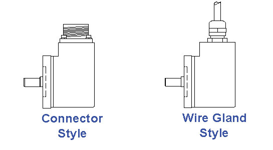
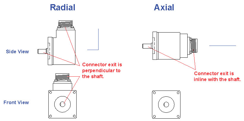
Both styles of electrical connections can exit the encoder either axially, or along the same axis as the encoder’s shaft, or radially, perpendicular to the shaft. Being able to choose this electrical connection exit method allows for the QDH20 encoder to fit into tight spaces.
Shaft Options:
Shafts options will either be a standard solid shaft or a hollow shaft. Keep in mind that the solid shafts go with the servo and flange style mount and the hollow shaft has a flex style mount.
Resolution options:
The QDH20 encoder currently can have resolutions (pulses per rotation) of up to 5000 direct read. (not interpolated).
The current QDH20 resolution options are:
200, 250, 256, 500, 512, 600, 1000, 1024, 1250, 2000, 2048, 2500, 3600, 4096 and 5000
These resolutions are all “direct read”, which means that the signals are taken right from the encoder disk, as opposed to interpolation which creates more pulses than are represented by the disk pattern. Direct read is always preferred if you can get it as there is one less error factor (Interpolation error) to worry about.
Output Options:
The electrical output that the QDH20 encoder can provide are either 5 to 26 Volt differential or single ended via the OL7272 line driver, or an Open Collector style.
The OL7272 has thermal and electrical overload protections built into it. The encoder is designed so that whatever voltage you put into the power rails you get out, minus a small voltage drop, on the signal wires.
Open collector style encoders require pull up resistors to make the signals work.
Channel Options:
This is used to select the style and number of output channels you need. This is the option that drives the style of connector the QDH20 will have.
Output Waveform Options:
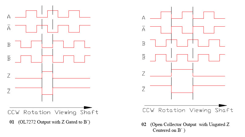
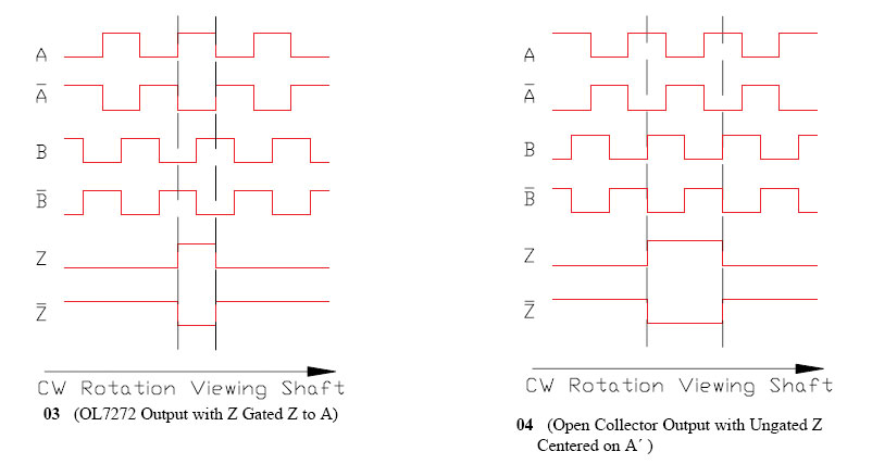
This option refers to the phasing relationships between the encoder channels. Some rotary encoder manufacturers have established traditional waveforms styles that their industrial encoders fall into.
The QDH20 waveform options 01 and 02 match exactly with certain BEI style encoders. QDH20 waveform options 03 and 04 match up with certain EPC style encoders.
While the many ways to configure a QDH20 Rotary Encoder can be confusing, hopefully looking at each option has made it a bit simpler to understand.

