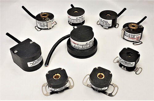
Quantum Devices, a United States based encoder manufacturer, designs and manufactures high quality, high performance incremental optical rotary encoders for a multitude of industries and applications.
View Our Encoders
We partner with OEM equipment manufacturers to provide application-specific encoders for servo motors, robotics and many other applications. We can accommodate special design requests and deliver custom solutions that add value to your equipment and automation systems.
Learn why Quantum Devices is uniquely positioned to provide OEM encoder solutions for your most challenging application:
Our high-performing encoders offer numerous configurations to meet a broad range of motion control requirements in manufacturing, simulation, printing and more. From medical labs to warehouse distribution centers, Quantum Devices encoders are used by some of the world’s largest companies.
Don’t see what you need in the specs? We can make it happen. We also manufacture custom photodiodes.
We offer a limited selection of encoders for sale online as a convenience for engineers and prototypers who need encoders with fast lead times for project development.
For high-volume orders, please contact us directly.
Quantum Devices offers free encoder product samples on a case-by-case basis. Our prototype sample encoders are manufactured to the same standards as our production units.
Please contact us to share your project and request samples for research and testing.
Quantum Devices has its roots in manufacturing silicon photodiodes. From online schematics to custom packaging for simplified assembly, we can supply all your electro-optical component needs.
Learn more about our photodiode manufacturing capabilities:
Unlike most encoder suppliers, Quantum Devices is a nimble and vertically integrated manufacturer. We pride ourselves on unmatched responsiveness to customer needs, including requests for custom-designed encoders.
Whether the encoder you need got obsoleted or doesn’t exist yet, we can help.
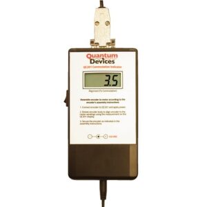
Now you can time an encoder to a motor statically, with no backdriving and no oscilloscope. This indicator gives a readout in electrical degrees and drastically reduces production time.
Learn More
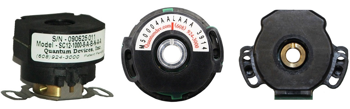
A technical comparison of our QM35 models against the competition. We open them up and show you exactly where better performance comes from.
Learn More
Samantha Lundt has worked as Quantum Devices’ Manufacturing Process Engineer for 5 years. She oversees our semiconductor cleanroom processes, which are currently undergoing an upgrade.
Learn More |
Looking for a RENCO replacement?We can help you replace RCML15, R35i, R22i, or other RENCO encoders, in addition to many other brands of rotary encoders. Contact Us |
 |
Find an Optical Encoder distributor!Quantum Devices is a leading manufacturer of optical encoders and silicon photodiodes. We have distributors all over the world. Find Distributor |
All of our products are proudly manufactured at our headquarters in Barneveld, Wisconsin.
Create an account to gain access to all of our 3D models!
Create an account to gain access to all of our 3D models!